I touched on the topic of metal bending and bend radii in my last blog post, Design 101. However, I thought it was imperative that I go deeper into the subject of minimum bend radii – focusing specifically on using bend notching in order to address issues of cutouts close to a bend, as well as how to work around bending constraints.
Rule of Thumb for Staying Clear of Bends
I often get asked by customers how far a cutout should be from a bend. This value is driven by the material type, thickness and tooling used to bend or bend radius required. Refer to our Material Bend Radii and Minimum Bend Size Chart for this value. Whatever minimum bend value you choose for your design, you must then make sure your cutouts are at least that same value from the bend. For example, if you are using 14 gauge Stainless Steel (A240 TP304 2B) and opt for a minimum bend of .275”, then your cutouts must be no closer than .275” to a bend. By using the minimum bend dimension value for your minimum closeness of cutout to a bend, you will ensure you don’t run into any issues.
Breaking our Rule
However, there are some instances where, in order to accomplish your design goals, it becomes necessary that you violate our simple rule of thumb, and place a cutout closer to a bend. For example, you may require openings for access to an internal component, or your design may need clear access to connectors through front panel cutouts. The problem is if you simply violate our minimum bend rule and place your cutout close to the bend, your cutout may stretch or flare. Once flared or stretched, the cutout will likely not be within tolerance, which in turn will cause the part to not bend properly, not to mention the fact that your component won’t fit within the cutout.
Notching
This problem can be easily averted by using notches to leave your cutout in perfect form. This blog post will explain notches and instances in which they are best used to solve design problems.
We’ve made a short video to illustrate the stretching problem and how notching can address it. In this video, we actually are solving two problems. First, we have a fan cutout that is too close to the bend line, and as you’ll see in the video, bending causes the cutout to flare and stretch. Secondly, the first approach didn’t allow room for the fan itself. You’ll see how we solved both problems in the video by notching away the full flange width. Note that if we didn’t need to fit the fan, we could have simply notched out the corner top of the bend to allow the cutout to fit properly, and left most of the flange intact.
Simple Notching for Cutouts Close to Bends
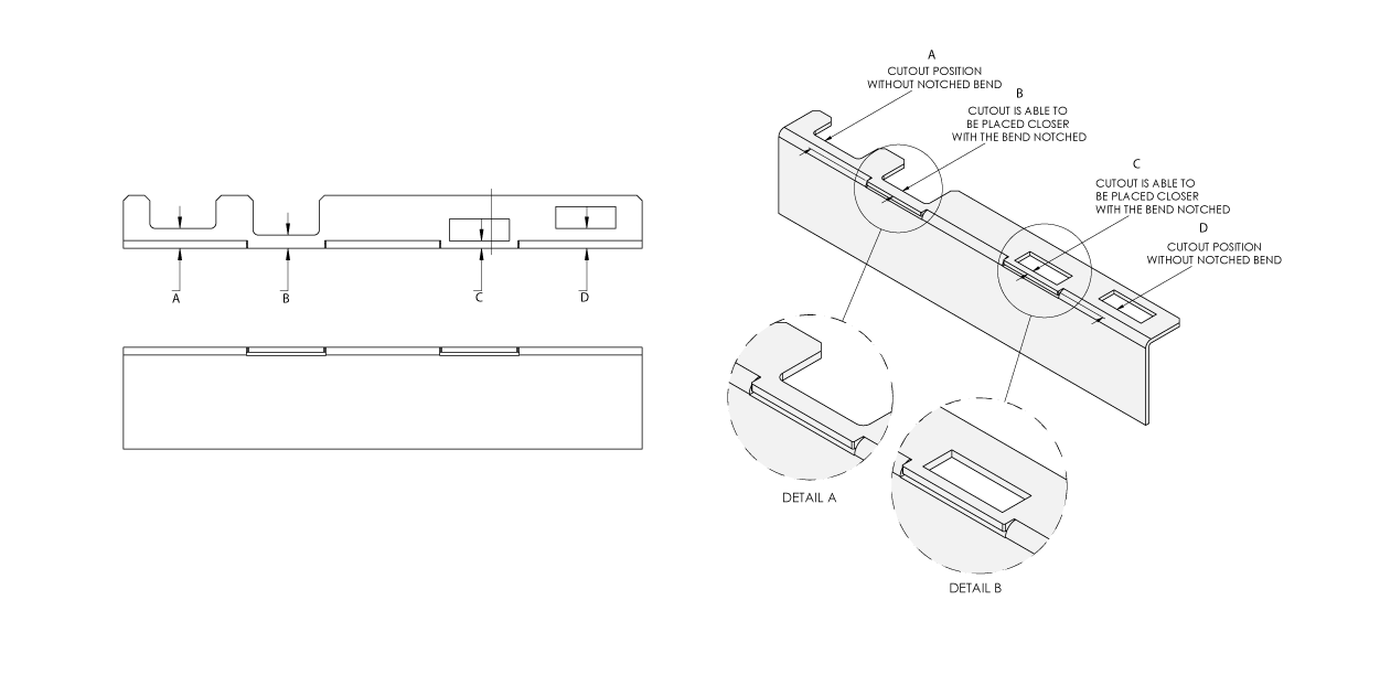
The diagram below shows a cutout placed so close to a bend, such that you’d expect the cutout to be stretched out and flared. But the bend has been notched in that particular area, giving the cutout more room, thus eliminating any stretching.

Below I have put together some practical examples of the use of notching to solve design problems.
Practical Examples of How Notches Can Be Used
- Get closer to the minimum bend:

This type of notched bend allows the cutout to be closer to the bend than the minimum bend on that material type/thickness. However, with this option, there will be a notch in the bottom of the case. This method is a great way to get your cutouts where you need them to be without sacrificing the overall accuracy of the design.
- Flange smaller than minimum bend:
There are some instances when a flange needs to be smaller than the minimum bend requirement, whether to allow access to a component below or for hardware insertion. In these cases, a notch can be helpful when a flange must be smaller than the minimum bend requirement for the material being used. The image below shows a flange that is smaller than the minimum bend for a material.

When it comes to rackmount enclosures, 1U rackmounts are the smallest in height. This means internal space within the enclosure is quite limited.
In the image below (as well as in the video I introduced earlier), you can see a 1U enclosure with its height maxed out at 1.72”. To accommodate the 40mm fan, the rear panel flanges have been sectioned, rather than going straight across.

- To accommodate standoffs and connectors:
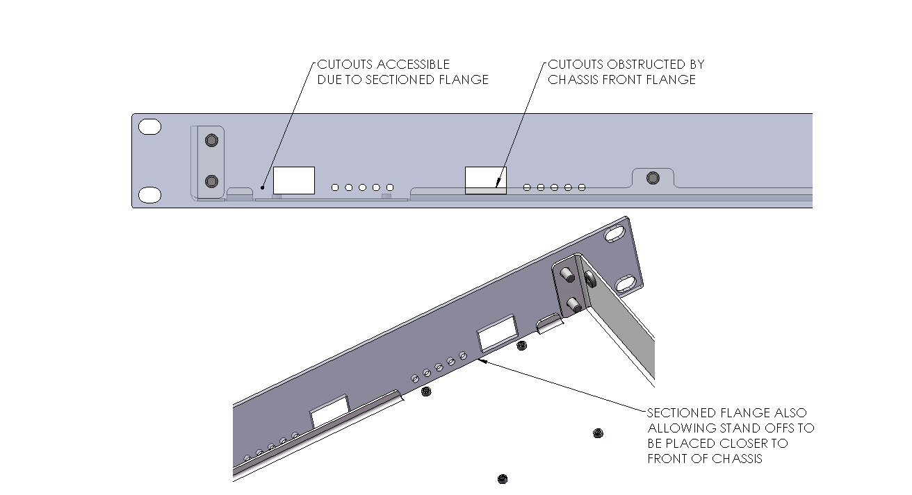
The images below show a 1U chassis with its front flange sectioned, using notching to accommodate two requirements:
- Allowing clear access to connectors through front panel cutouts
- Stand-offs are able to be positioned closer to the front edge of the chassis

Extra Tip: Another application for notching is to place cutouts close to an edge to allow tools to access internal components. This is just a special case of a cutout being situated close to, or on top of, a bend.
Using Notches in Enclosures that Accommodate PCI Cards:
If your design requires you to mount a PCI (Peripheral Component Interconnect) Card, you may need to accommodate extra space around it to provide relief for connectors that may protrude the PCI bracket.
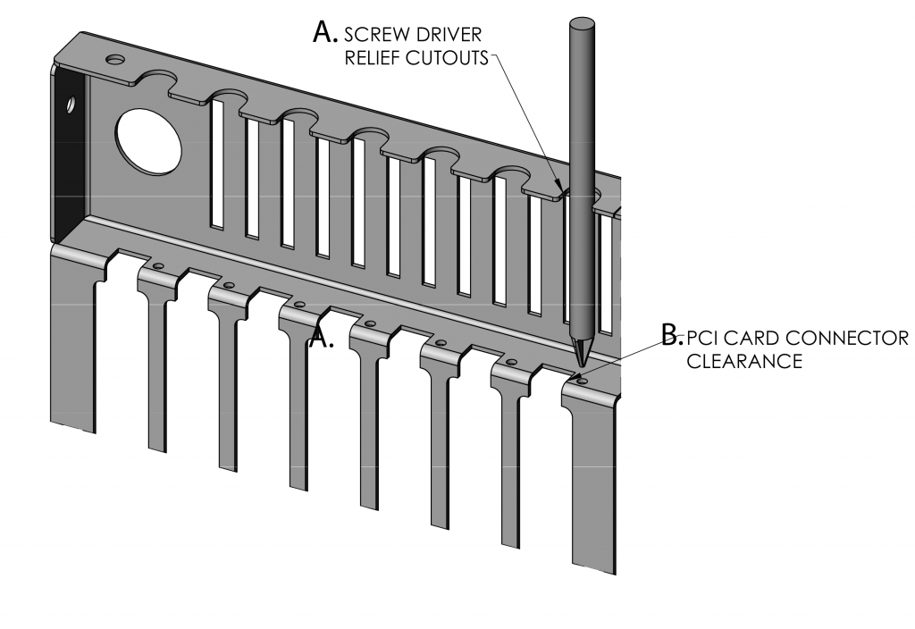
This image shows two different uses for bend notching:

The first (A, pictured) is a screwdriver relief cutout – slots added on top of the flange to allow access to screws used to fasten PCI cards in flange below. This ensures the person installs the screws correctly, as it prevents them from trying to insert a screw into the tapped hole below using the screwdriver in an angled position. Using the screwdriver in the vertical position reduces the chance of stripping the screw.
The second (B) is a notch into bend to provide relief for connectors that may protrude the PCI bracket. Some PCI cards come with protruding connectors, and this bend cut provides clearance for those connectors, which allows the designer to install the card more easily.
Making Notches in Protocase Designer
Follow these steps to create notches on the edge of faces using Protocase Designer, our own 3D enclosure design software that’s free and simple to use.
- Open your preferences by clicking Edit in the top menu, then select Preferences from the drop-down menu. Click on Editor Settings tab. For Error Response, select ASK from the drop down. Click Finish.
- Click Edit Face, and select the face where you would like to create a notch.
- In the Face Editor, create a cutout the size and shape of the notch you want, but extend it further past the edge of the face you are notching.
- You will receive a warning that the cutout intersects the Face’s boundary. Click “Accept and Do Not Cut Face.”
- Move your cutout to the exact location where you would like to notch. You will receive the warning about the cutout intersecting the Face’s boundary. Click “Accept and Do Not Cut Face.”
- Once you are satisfied with the placement of your cutout that will become a notch, click Cut Face, which can be found on the right toolbar. Accept changes.
Conclusion
I hope this blog post has helped to clarify design issues surrounding cutouts and components that must be placed in close proximity to a bend and how notching can be used to solve certain design dilemmas that arise. However, if you run into another scenario where you think notching may help accommodate your vision, or you would like to discuss any other issues around sheet metal or enclosure design, please contact us.
As always, we welcome any feedback you may have, so feel free to comment below.


